
Grating for Industrial Strength and Safety
Oasis Metal, Press Welded Gratings are engineered to deliver unmatched strength, stability, and performance in demanding environments. Manufactured by forge-welding bearing bars and cross-rods under pressure, this process creates a rigid, one-piece grating panel with exceptional load-bearing capacity and durability.
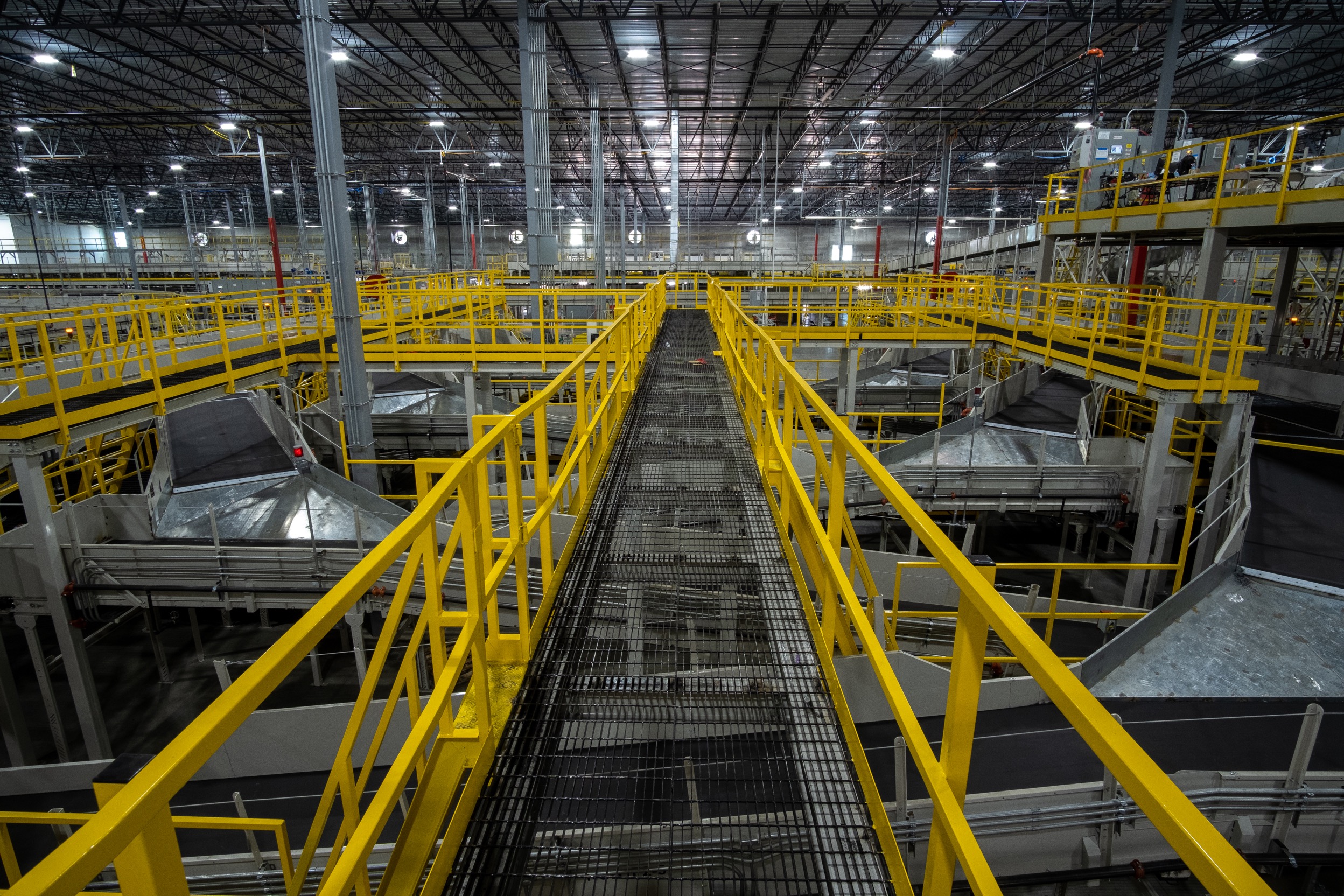
These gratings are designed for use in multiple applications, where structural reliability and safety are critical. The secure welded joints create a rigid grid that withstands heavy rolling loads, high pedestrian traffic, and corrosive environments – making press welded gratings our most popular and trusted solution.
Key Features

Forge-Welded Joints for Maximum Strength
Each panel is constructed through an automated forge-welding process where the cross-rods are permanently fused to the bearing bars. This results in an integrated structure capable of withstanding heavy industrial loads, including forklift and vehicle traffic.

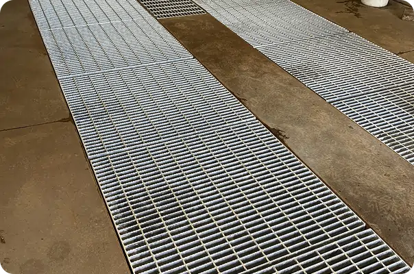
Slip-Resistant Surface Options
To suit various environments, our press welded gratings are available with either a plain surface for smooth applications or a serrated surface for improved slip resistance. Serrated bearing bars are ideal for areas exposed to water, oil, or other potential hazards where safe footing is essential.

Corrosion Protection Through Galvanization
Every grating can be hot-dipped galvanized after fabrication, providing a durable zinc coating that protects the steel from corrosion. This is especially important in outdoor, marine, or chemical plant environments where longevity can be a concern.

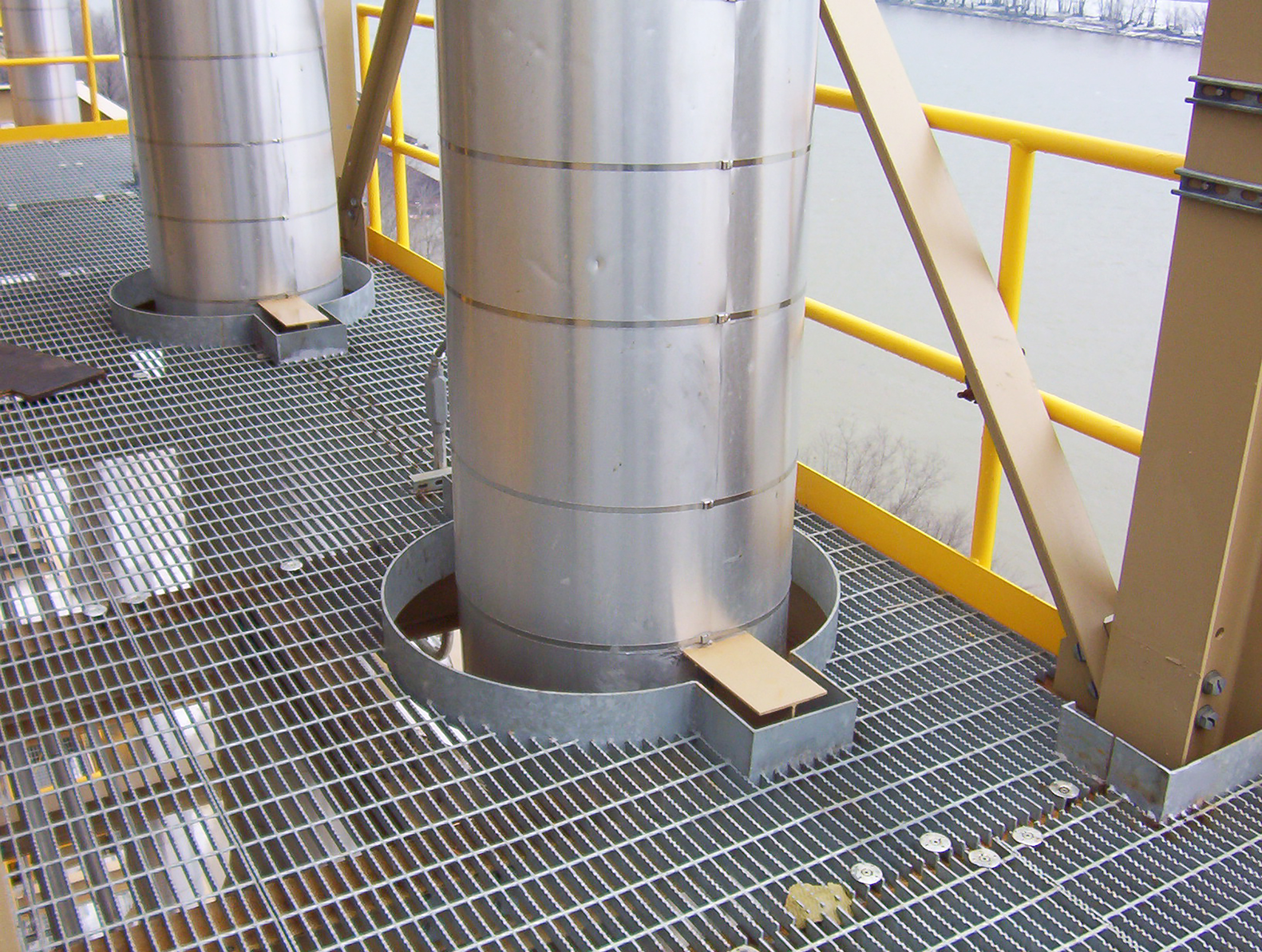
Built for Heavy Loads and Harsh Conditions
With their rigid construction and deep bearing bars, press welded gratings offer excellent performance in areas subject to repetitive loading, vibration, or dynamic forces. They are commonly used in settings such as vehicle service bays, mining walkways, and industrial platforms.
Common Applications
Press welded gratings are a go-to solution across multiple sectors due to their unmatched strength and reliability.
Oil, gas, and mining infrastructure
Industrial flooring in factories or plants
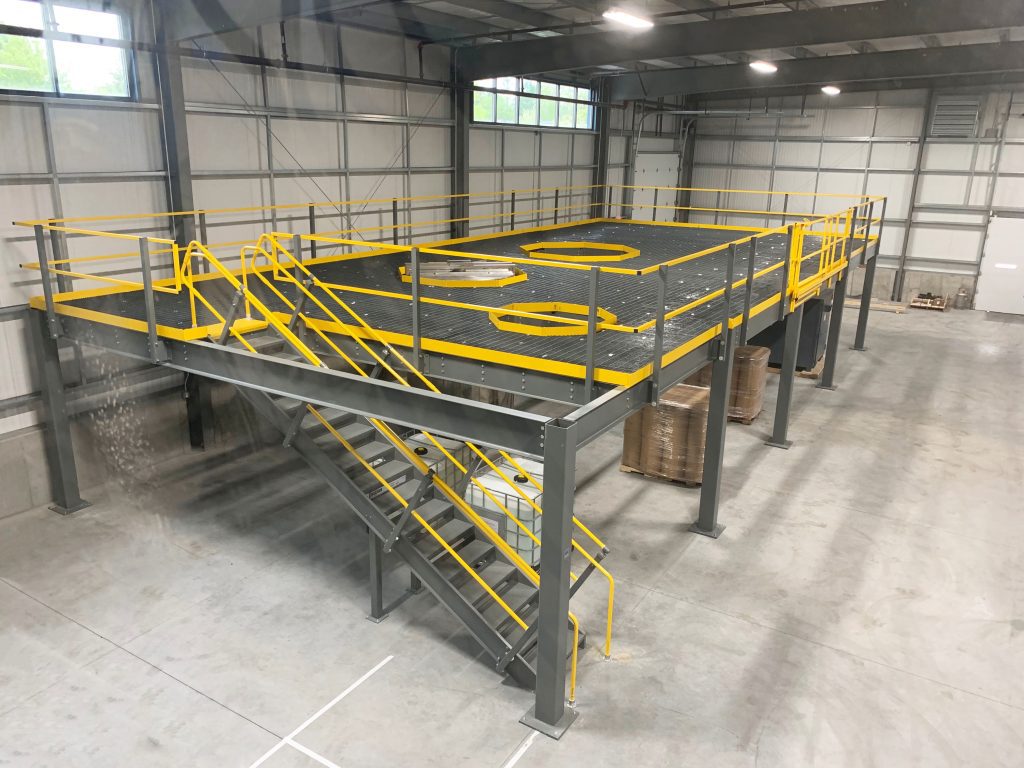
Access platforms and service walkways
Vehicle maintenance pits
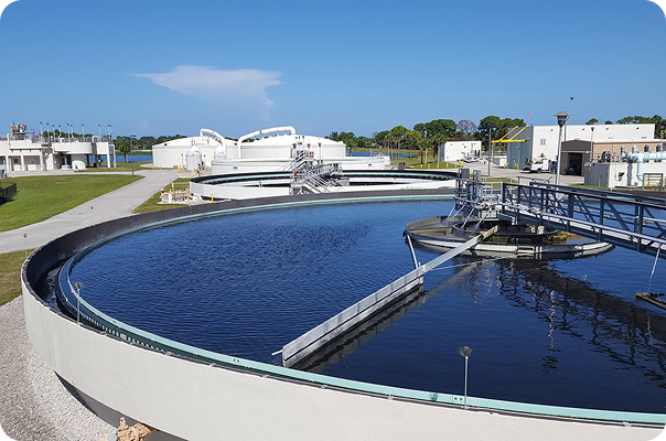
Wastewater treatment facilities
Benefits of Press Welded Gratings
Long-Term Durability
Engineered to perform in extreme conditions, press welded gratings offer an exceptionally long service life. Their forged-welded process ensures that a high structural integrity remains intact even after years of exposure to heavy loads and weathering.
Resistance to Environmental Stressors
With the option of galvanisation and chemical-resistant coatings, these gratings are resilient against corrosion, and inclement weather. This makes them ideal for use in corrosive or outdoor environments where conventional flooring solutions would degrade quickly.
Custom Fabrication Available
Each project can be customized to your specifications. We offer various bearing bar sizes, thicknesses, and spacings to meet specific load requirements or project constraints. Panels can also be cut to size, shaped to fit irregular layouts, and manufactured with cut-outs for integration with existing structural steel.
Low Maintenance, High Safety
The open grid design ensures efficient drainage and debris flow-through, helping to keep surfaces clean and slip-resistant with minimal maintenance. The solid steel construction means these panels require very little upkeep, reducing lifecycle costs and operational downtime.
Technical Specifications
Material
- Mild Steel
- Stainless Steel
Finish
- Hot-Dip Galvanized
- Painted
- Untreated for secondary processing
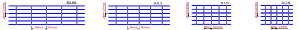
- Performance Table A
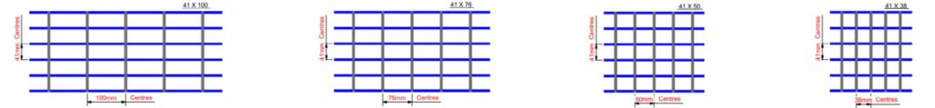
For 25mm Centres - Performance Table B
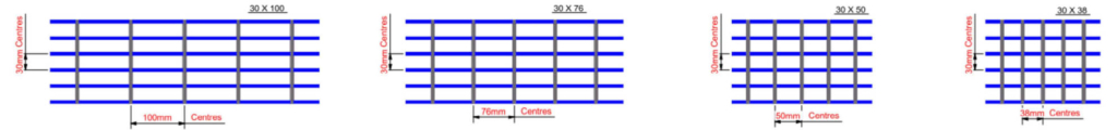
For 30mm Centres - Performance Table C
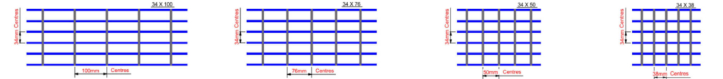
For 34mm Centres - Performance Table D
For 41mm Centres
NOTES: Below table is made considering working stress of 165 N/mm2 which allows for a safety factor of 1.6
Deflection should not more than span / 200 times or 10mm, whichever is lesser
For pedestrian traffic there are three loading categories, which are Light Duty – (UDL – 3 KN/m2), Medium Duty- (UDL- 5 KN/m2), and Heavy Duty- (UDL – 7 5 KN/m2)
Add 2 8 Kg/m2 to theoretical weight Kg/m2 for Cross bars @ 50 mm centres
When calculating UDL and deflection for serrated gratings, allowance should be made for the material removed from the bearing bar to form the serration profile Typically this is 90% of the UDL and 105% of the deflection. These figures vary depending on the type of serration and should be confirmed during the design process.
| Bearing Bar Size (mm) | SPAN IN MM | Max Clear Span for Pedestrian Loadings | Theoritical Weight Kg/m² for 100mm pitch | ||||||||||||||||
|---|---|---|---|---|---|---|---|---|---|---|---|---|---|---|---|---|---|---|---|
| 300 | 450 | 600 | 750 | 900 | 1050 | 1200 | 1350 | 1500 | 1650 | 1800 | 1950 | 2100 | U-KN/m2 | 3 | 5 | 7.5 | |||
| 20 x 3 | UDL-KN/m² | 120.60 | 53.36 | 30.05 | 15.44 | 8.93 | 5.62 | 3.76 | 2.64 | 1.93 | 1.44 | 1.11 | 0.87 | 0.67 | Span – mm | 1295 | 1092 | 954 | 22.14 |
| D – mm | 0.75 | 1.68 | 2.99 | 3.75 | 4.50 | 5.25 | 6.00 | 6.75 | 7.50 | 8.25 | 9.00 | 9.75 | 10.00 | D – mm | 6.47 | 5.46 | 4.77 | ||
| 20 x 5 | UDL-KN/m² | 201.00 | 88.90 | 50.08 | 25.73 | 14.89 | 9.38 | 6.28 | 4.41 | 3.21 | 2.41 | 1.86 | 1.46 | 1.11 | Span – mm | 1535 | 1294 | 1131 | 35.01 |
| D – mm | 0.75 | 1.68 | 2.99 | 3.75 | 4.50 | 5.25 | 6.00 | 6.75 | 7.50 | 8.25 | 9.00 | 9.75 | 10.00 | D – mm | 7.67 | 6.47 | 5.65 | ||
| 25 x 3 | UDL-KN/m² | 188.50 | 83.70 | 47.00 | 30.10 | 17.45 | 10.99 | 7.36 | 5.17 | 3.77 | 2.83 | 2.18 | 1.71 | 1.30 | Span – mm | 1618 | 1365 | 1192 | 26.96 |
| D – mm | 0.60 | 1.35 | 2.39 | 3.75 | 4.50 | 5.25 | 6.00 | 6.75 | 7.50 | 8.25 | 9.00 | 9.75 | 10.00 | D – mm | 8.09 | 6.82 | 5.96 | ||
| 25 x 5 | UDL-KN/m² | 314.00 | 139.60 | 78.20 | 50.12 | 29.08 | 18.31 | 12.27 | 8.61 | 6.28 | 4.72 | 3.63 | 2.86 | 2.18 | Span – mm | 1919 | 1618 | 1414 | 43.06 |
| D – mm | 0.60 | 1.35 | 2.39 | 3.75 | 4.50 | 5.25 | 6.00 | 6.75 | 7.50 | 8.25 | 9.00 | 9.75 | 10.00 | D – mm | 9.60 | 8.09 | 7.07 | ||
| 30 x 3 | UDL-KN/m² | 271.50 | 120.10 | 67.50 | 43.35 | 30.08 | 18.99 | 12.72 | 8.93 | 6.51 | 4.89 | 3.77 | 2.96 | 2.26 | Span – mm | 1942 | 1638 | 1431 | 31.79 |
| D – mm | 0.50 | 1.12 | 1.99 | 3.12 | 4.49 | 5.25 | 6.00 | 6.75 | 7.50 | 8.25 | 9.00 | 9.75 | 10.00 | D – mm | 9.71 | 8.19 | 7.15 | ||
| 30 x 5 | UDL-KN/m² | 452.00 | 200.10 | 112.50 | 72.30 | 50.15 | 31.65 | 21.20 | 14.89 | 10.85 | 8.15 | 6.28 | 4.94 | 3.76 | Span – mm | 2223 | 1942 | 1697 | 51.10 |
| D – mm | 0.50 | 1.12 | 1.99 | 3.12 | 4.49 | 5.25 | 6.00 | 6.75 | 7.50 | 8.25 | 9.00 | 9.75 | 10.00 | D – mm | 10.00 | 9.71 | 8.48 | ||
| 35 x 3 | UDL-KN/m² | 371.00 | 163.50 | 92.10 | 58.90 | 40.97 | 30.09 | 20.20 | 14.19 | 10.34 | 7.77 | 5.99 | 4.70 | 3.58 | Span – mm | 2196 | 1911 | 1669 | 36.62 |
| D – mm | 0.43 | 0.96 | 1.71 | 2.67 | 3.85 | 5.24 | 6.00 | 6.75 | 7.50 | 8.25 | 9.00 | 9.75 | 10.00 | D – mm | 10.00 | 9.55 | 8.34 | ||
| 35 x 5 | UDL-KN/m² | 617.00 | 272.50 | 153.50 | 98.20 | 68.28 | 50.16 | 33.66 | 23.64 | 17.23 | 12.95 | 9.97 | 7.85 | 5.98 | Span – mm | 2495 | 2196 | 1980 | 59.15 |
| D – mm | 0.43 | 0.96 | 1.71 | 2.67 | 3.85 | 5.24 | 6.00 | 6.75 | 7.50 | 8.25 | 9.00 | 9.75 | 10.00 | D – mm | 10.00 | 10.00 | 9.90 | ||
| 40 x 3 | UDL-KN/m² | 476.00 | 213.50 | 120.60 | 77.06 | 53.52 | 39.26 | 3.05 | 21.18 | 15.44 | 11.60 | 8.93 | 7.02 | 5.35 | Span – mm | 2427 | 2136 | 1908 | 41.45 |
| D – mm | 0.37 | 0.84 | 1.50 | 2.34 | 3.37 | 4.58 | 5.98 | 6.75 | 7.50 | 8.25 | 9.00 | 9.75 | 10.00 | D – mm | 10.00 | 10.00 | 9.54 | ||
| 40 x 5 | UDL-KN/m² | 793.00 | 355.60 | 201.00 | 128.47 | 89.20 | 65.44 | 50.09 | 35.29 | 25.73 | 19.33 | 14.89 | 11.71 | 8.93 | Span – mm | 2758 | 2427 | 2194 | 67.20 |
| D – mm | 0.37 | 0.84 | 1.50 | 2.34 | 3.37 | 4.58 | 5.98 | 6.75 | 7.50 | 8.25 | 9.00 | 9.75 | 10.00 | D – mm | 10.00 | 10.00 | 10.00 | ||
| 50 x 5 | UDL-KN/m² | 1255.00 | 554.00 | 314.00 | 200.50 | 139.10 | 102.15 | 78.36 | 61.89 | 50.25 | 37.75 | 29.08 | 22.87 | 17.44 | Span – mm | 3260 | 2870 | 2593 | 83.29 |
| D – mm | 0.30 | 0.67 | 1.20 | 1.87 | 2.69 | 3.66 | 4.79 | 6.06 | 7.50 | 8.25 | 9.00 | 9.75 | 10.00 | D – mm | 10.00 | 10.00 | 10.00 | ||
| 60 x 5 | UDL-KN/m² | 1810.00 | 800.00 | 452.50 | 289.00 | 200.10 | 147.10 | 112.80 | 89.12 | 72.13 | 65.25 | 50.25 | 39.53 | 30.14 | Span – mm | 3738 | 3290 | 2973 | 99.38 |
| D – mm | 0.25 | 0.56 | 1.00 | 1.56 | 2.24 | 3.05 | 3.99 | 5.05 | 6.23 | 8.25 | 9.00 | 9.75 | 10.00 | D – mm | 10.00 | 10.00 | 10.00 | ||
| 70 x 5 | UDL-KN/m² | 2415.00 | 1090.00 | 610.50 | 394.20 | 272.34 | 200.60 | 153.50 | 121.35 | 98.19 | 81.12 | 79.80 | 62.76 | 47.86 | Span – mm | 4197 | 3693 | 3337 | 115.47 |
| D – mm | 0.21 | 0.48 | 0.85 | 1.34 | 1.92 | 2.62 | 3.42 | 4.33 | 5.34 | 6.46 | 9.00 | 9.75 | 10.00 | D – mm | 10.00 | 10.00 | 10.00 | ||
NOTES: Below table is made considering working stress of 165 N/mm2′ which allows for a safety factor of 1.6
Deflection should not more than span / 200 times or 10mm, whichever is lesser
For pedestrian traffic there are three loading categories. which are Light Duty – (UDL – 3 KN/m2), Medium Duty – (UDL – 5 KN/m2) and Heavy Duty – (UDL – 7 5 KN/m2)
Add 2 8 Kg/m2 to theoretical weight Kg/m2 for Cross bars @ 50 mm centres
When calculating UDL and deflection for serrated gratings, allowance should be made for the material removed from the bearing bar to form the serration profile Typically this is 90% of the UDL and 105% of the deflection. These figures vary depending on the type of serration and should be confirmed during the design process.
| Bearing Bar Size (mm) | SPAN IN MM | Max Clear Span for Pedestrian Loadings | Theoritical Weight Kg/m² for 100mm pitch | ||||||||||||||||
|---|---|---|---|---|---|---|---|---|---|---|---|---|---|---|---|---|---|---|---|
| 300 | 450 | 600 | 750 | 900 | 1050 | 1200 | 1350 | 1500 | 1650 | 1800 | 1950 | 2100 | U-KN/m2 | 3 | 5 | 7.5 | |||
| 20 x 3 | UDL-KN/m² | 99.73 | 44.33 | 24.93 | 12.80 | 7.41 | 4.67 | 3.13 | 2.20 | 1.60 | 1.20 | 0.93 | 0.73 | 0.56 | Span-mm | 1217 | 1026 | 896 | 18.84 |
| D – mm | 0.75 | 1.68 | 2.99 | 3.75 | 4.50 | 5.25 | 6.00 | 6.75 | 7.50 | 8.25 | 9.00 | 9.75 | 10.00 | D – mm | 6.09 | 5.13 | 4.48 | ||
| 20 x 5 | UDL-KN/m² | 166.22 | 73.88 | 41.56 | 21.34 | 12.35 | 7.78 | 5.21 | 3.66 | 2.67 | 2.00 | 1.54 | 1.21 | 0.93 | Span – mm | 1442 | 1217 | 1063 | 29.52 |
| D – mm | 0.75 | 1.68 | 2.99 | 3.75 | 4.50 | 5.25 | 6.00 | 6.75 | 7.50 | 8.25 | 9.00 | 9.75 | 10.00 | D – mm | 7.21 | 6.09 | 5.32 | ||
| 25 x 3 | UDL-KN/m² | 155.83 | 69.26 | 38.96 | 24.93 | 14.47 | 9.11 | 6.10 | 4.29 | 3.13 | 2.35 | 1.81 | 1.42 | 1.08 | Span – mm | 1521 | 1283 | 1120 | 22.84 |
| D – mm | 0.60 | 1.35 | 2.39 | 3.74 | 4.50 | 5.25 | 6.00 | 6.75 | 7.50 | 8.25 | 9.00 | 9.75 | 10.00 | D – mm | 7.61 | 6.42 | 5.60 | ||
| 25 x 5 | UDL-KN/m² | 259.72 | 115.43 | 64.93 | 41.56 | 24.12 | 15.19 | 10.17 | 7.15 | 5.21 | 3.91 | 3.01 | 2.37 | 1.81 | Span – mm | 1803 | 1521 | 1328 | 36.19 |
| D – mm | 0.60 | 1.35 | 2.39 | 3.74 | 4.50 | 5.25 | 6.00 | 6.75 | 7.50 | 8.25 | 9.00 | 9.75 | 10.00 | D – mm | 9.02 | 7.61 | 6.64 | ||
| 30 x 3 | UDL-KN/m² | 224.40 | 99.73 | 56.10 | 35.90 | 24.93 | 15.75 | 10.55 | 7.41 | 5.40 | 4.06 | 3.13 | 2.46 | 1.87 | Span – mm | 1825 | 1539 | 1345 | 26.85 |
| D – mm | 0.50 | 1.12 | 1.99 | 3.12 | 4.49 | 5.25 | 6.00 | 6.75 | 7.50 | 8.25 | 9.00 | 9.75 | 10.00 | D – mm | 9.13 | 7.70 | 6.73 | ||
| 30 x 5 | UDL-KN/m² | 374.00 | 166.22 | 93.50 | 59.84 | 41.56 | 26.24 | 17.58 | 12.35 | 9.00 | 6.76 | 5.21 | 4.10 | 3.12 | Span – mm | 2121 | 1825 | 1594 | 42.86 |
| D – mm | 0.50 | 1.12 | 1.99 | 3.12 | 4.49 | 5.25 | 6.00 | 6.75 | 7.50 | 8.25 | 9.00 | 9.75 | 10.00 | D – mm | 10.00 | 9.13 | 7.97 | ||
| 35 x 3 | UDL-KN/m² | 305.43 | 135.75 | 76.36 | 48.87 | 33.94 | 24.93 | 16.75 | 11.76 | 8.58 | 6.44 | 4.96 | 3.90 | 2.98 | Span – mm | 2096 | 1796 | 1569 | 30.85 |
| D – mm | 0.43 | 0.96 | 1.71 | 2.67 | 3.85 | 5.24 | 6.00 | 6.75 | 7.50 | 8.25 | 9.00 | 9.75 | 10.00 | D – mm | 10.00 | 8.98 | 7.85 | ||
| 35 x 5 | UDL-KN/m² | 509.06 | 226.25 | 127.26 | 81.45 | 56.56 | 41.56 | 27.92 | 19.61 | 14.29 | 10.74 | 8.27 | 6.51 | 4.96 | Span – mm | 2381 | 2096 | 1860 | 49.53 |
| D – mm | 0.43 | 0.96 | 1.71 | 2.67 | 3.85 | 5.24 | 6.00 | 6.75 | 7.50 | 8.25 | 9.00 | 9.75 | 10.00 | D – mm | 10.00 | 10.00 | 9.30 | ||
| 40 x 3 | UDL-KN/m² | 398.93 | 177.30 | 99.73 | 63.83 | 44.33 | 32.57 | 24.93 | 17.56 | 12.80 | 9.62 | 7.41 | 5.83 | 4.44 | Span – mm | 2317 | 2039 | 1793 | 34.85 |
| D – mm | 0.37 | 0.84 | 1.50 | 2.34 | 3.37 | 4.58 | 5.98 | 6.75 | 7.50 | 8.25 | 9.00 | 9.75 | 10.00 | D – mm | 10.00 | 10.00 | 8.97 | ||
| 40 x 5 | UDL-KN/m² | 664.89 | 295.51 | 166.22 | 106.38 | 73.88 | 54.28 | 41.56 | 29.27 | 21.34 | 16.03 | 12.35 | 9.71 | 7.41 | Span – mm | 2632 | 2317 | 2093 | 56.21 |
| D – mm | 0.37 | 0.84 | 1.50 | 2.34 | 3.37 | 4.58 | 5.98 | 6.75 | 7.50 | 8.25 | 9.00 | 9.75 | 10.00 | D – mm | 10.00 | 10.00 | 10.00 | ||
| 50 x 5 | UDL-KN/m² | 1038.89 | 461.73 | 259.72 | 166.22 | 115.43 | 84.81 | 64.93 | 51.30 | 41.67 | 31.31 | 24.12 | 18.97 | 14.46 | Span – mm | 3112 | 2739 | 2475 | 69.55 |
| D – mm | 0.30 | 0.67 | 1.20 | 1.87 | 2.69 | 3.66 | 4.79 | 6.06 | 7.50 | 8.25 | 9.00 | 9.75 | 10.00 | D – mm | 10.00 | 10.00 | 10.00 | ||
| 60 x 5 | UDL-KN/m² | 1496.00 | 664.89 | 374.00 | 239.36 | 166.22 | 122.12 | 93.50 | 73.88 | 59.84 | 54.10 | 41.67 | 32.78 | 24.99 | Span – mm | 3568 | 3140 | 2837 | 82.90 |
| D – mm | 0.25 | 0.56 | 1.00 | 1.56 | 2.24 | 3.05 | 3.99 | 5.05 | 6.23 | 8.25 | 9.00 | 9.75 | 10.00 | D – mm | 10.00 | 10.00 | 10.00 | ||
| 70 x 5 | UDL-KN/m² | 2036.22 | 904.99 | 509.06 | 325.80 | 226.25 | 166.22 | 127.26 | 100.55 | 81.45 | 67.31 | 66.18 | 52.05 | 39.69 | Span – mm | 4005 | 3525 | 3185 | |
| D – mm | 0.21 | 0.48 | 0.85 | 1.34 | 1.92 | 2.62 | 3.42 | 4.33 | 5.34 | 6.46 | 9.00 | 9.75 | 10.00 | D – mm | 10.00 | 10.00 | 10.00 | ||
NOTES: Below table is made considering working stress of 165 N/mm2′ which allows for a safety factor of 1.6
Deflection should not more than span/ 200 times or 10mm, whichever is lesser
For pedestrian traffic there are three loading categories, which are Light Duty – (UDL – 3 KN/m2), Medium Duty – (UDL – 5 KN/m2) and Heavy Duty – (UDL – 7 5 KN/m2) Add 2 8 Kgim’ to theoretical weight Kgim’ for Cross bars @ 50 mm centres
When calculating UDL and deflection for serrated gratings, allowance should be made for the material removed from the bearing bar to form the serration profile Typically this is 90% of the UDL and 105% of the deflection. These figures vary depending on the type of serration and should be confirmed during the design process.
| Bearing Bar Size (mm) | SPAN IN MM | Max Clear Span for Pedestrian Loadings | Theoritical Weight Kg/m² for 100mm pitch | ||||||||||||||||
|---|---|---|---|---|---|---|---|---|---|---|---|---|---|---|---|---|---|---|---|
| 300 | 450 | 600 | 750 | 900 | 1050 | 1200 | 1350 | 1500 | 1650 | 1800 | 1950 | 2100 | U-KN/m2 | 3 | 5 | 7.5 | |||
| 20 x 3 | UDL-KN/m² | 88.30 | 39.05 | 21.99 | 11.29 | 6.53 | 4.12 | 2.76 | 1.93 | 1.41 | 1.06 | 0.81 | 0.64 | 0.49 | Span-mm | 1166 | 984 | 860 | 16.96 |
| D – mm | 0.75 | 1.68 | 2.99 | 3.75 | 4.50 | 5.25 | 6.00 | 6.75 | 7.50 | 8.25 | 9.00 | 9.75 | 10.00 | D – mm | 5.83 | 4.92 | 4.29 | ||
| 20 x 5 | UDL-KN/m² | 147.00 | 65.10 | 36.65 | 18.83 | 10.90 | 6.86 | 4.60 | 3.23 | 2.35 | 1.76 | 1.36 | 1.07 | 0.81 | Span-mm | 1383 | 1167 | 1019 | 26.38 |
| D – mm | 0.75 | 1.68 | 2.99 | 3.75 | 4.50 | 5.25 | 6.00 | 6.75 | 7.50 | 8.25 | 9.00 | 9.75 | 10.00 | D – mm | 6.91 | 5.83 | 5.09 | ||
| 25 x 3 | UDL-KN/m² | 138.00 | 61.30 | 34.33 | 22.00 | 12.76 | 8.04 | 5.39 | 3.78 | 2.76 | 2.07 | 1.59 | 1.25 | 0.95 | Span-mm | 1459 | 1230 | 1074 | 20.49 |
| D – mm | 0.60 | 1.35 | 2.39 | 3.75 | 4.50 | 5.25 | 6.00 | 6.75 | 7.50 | 8.25 | 9.00 | 9.75 | 10.00 | D – mm | 7.29 | 6.15 | 5.37 | ||
| 25 x 5 | UDL-KN/m² | 230.00 | 102.15 | 57.21 | 36.67 | 21.28 | 13.40 | 8.97 | 6.30 | 4.59 | 3.45 | 2.66 | 2.09 | 1.59 | Span-mm | 1729 | 1459 | 1274 | 32.26 |
| D – mm | 0.60 | 1.35 | 2.39 | 3.75 | 4.50 | 5.25 | 6.00 | 6.75 | 7.50 | 8.25 | 9.00 | 9.75 | 10.00 | D – mm | 8.64 | 7.29 | 6.37 | ||
| 30 x 3 | UDL-KN/m² | 198.50 | 87.85 | 49.40 | 31.72 | 22.02 | 13.89 | 9.31 | 6.53 | 4.77 | 3.58 | 2.76 | 2.16 | 1.65 | Span-mm | 1750 | 1476 | 1290 | 24.02 |
| D – mm | 0.50 | 1.12 | 1.99 | 3.12 | 4.49 | 5.25 | 6.00 | 6.75 | 7.50 | 8.25 | 9.00 | 9.75 | 10.00 | D – mm | 8.75 | 7.38 | 6.44 | ||
| 30 x 5 | UDL-KN/m² | 331.00 | 146.40 | 82.40 | 52.86 | 36.77 | 23.15 | 15.51 | 10.89 | 7.94 | 5.96 | 4.60 | 3.61 | 2.75 | Span-mm | 2056 | 1750 | 1529 | 38.15 |
| D – mm | 0.50 | 1.12 | 1.99 | 3.12 | 4.49 | 5.25 | 6.00 | 6.75 | 7.50 | 8.25 | 9.00 | 9.75 | 10.00 | D – mm | 10.00 | 8.75 | 7.64 | ||
| 35 x 3 | UDL-KN/m² | 271.00 | 119.60 | 67.40 | 43.10 | 29.97 | 22.02 | 14.78 | 10.38 | 7.57 | 5.68 | 4.38 | 3.44 | 2.62 | Span-mm | 2031 | 1722 | 1504 | 27.55 |
| D – mm | 0.43 | 0.96 | 1.71 | 2.67 | 3.85 | 5.24 | 6.00 | 6.75 | 7.50 | 8.25 | 9.00 | 9.75 | 10.00 | D – mm | 10.00 | 8.61 | 7.52 | ||
| 35 x 5 | UDL-KN/m² | 452.00 | 199.30 | 112.30 | 71.85 | 49.96 | 36.70 | 24.64 | 17.30 | 12.61 | 9.47 | 7.30 | 5.74 | 4.37 | Span-mm | 2308 | 2031 | 1783 | 44.04 |
| D – mm | 0.43 | 0.96 | 1.71 | 2.67 | 3.85 | 5.24 | 6.00 | 6.75 | 7.50 | 8.25 | 9.00 | 9.75 | 10.00 | D – mm | 10.00 | 10.00 | 8.91 | ||
| 40 x 3 | UDL-KN/m² | 348.00 | 156.20 | 88.25 | 56.38 | 39.16 | 28.73 | 21.99 | 15.49 | 11.29 | 8.48 | 6.54 | 5.14 | 3.92 | Span-mm | 2245 | 1968 | 1719 | 31.09 |
| D – mm | 0.37 | 0.84 | 1.50 | 2.34 | 3.37 | 4.58 | 5.98 | 6.75 | 7.50 | 8.25 | 9.00 | 9.75 | 10.00 | D – mm | 10.00 | 9.84 | 8.59 | ||
| 40 x 5 | UDL-KN/m² | 580.00 | 260.20 | 147.10 | 94.00 | 65.28 | 47.88 | 36.65 | 25.83 | 18.83 | 14.14 | 10.89 | 8.57 | 6.53 | Span-mm | 2551 | 2245 | 2029 | 49.93 |
| D – mm | 0.37 | 0.84 | 1.50 | 2.34 | 3.37 | 4.58 | 5.98 | 6.75 | 7.50 | 8.25 | 9.00 | 9.75 | 10.00 | D – mm | 10.00 | 10.00 | 10.00 | ||
| 50 x 5 | UDL-KN/m² | 920.00 | 405.50 | 229.90 | 146.70 | 101.78 | 74.74 | 57.34 | 45.28 | 36.77 | 27.62 | 21.28 | 16.73 | 12.76 | Span-mm | 3015 | 2654 | 2398 | 61.70 |
| D – mm | 0.30 | 0.67 | 1.20 | 1.87 | 2.69 | 3.66 | 4.79 | 6.06 | 7.50 | 8.25 | 9.00 | 9.75 | 10.00 | D – mm | 10.00 | 10.00 | 10.00 | ||
| 60 x 5 | UDL-KN/m² | 1325.00 | 586.00 | 331.00 | 211.50 | 146.40 | 107.61 | 82.50 | 65.21 | 52.78 | 47.74 | 36.77 | 28.92 | 22.05 | Span-mm | 3457 | 3043 | 2750 | 73.48 |
| D – mm | 0.25 | 0.56 | 1.00 | 1.56 | 2.24 | 3.05 | 3.99 | 5.05 | 6.23 | 8.25 | 9.00 | 9.75 | 10.00 | D – mm | 10.00 | 10.00 | 10.00 | ||
| 70 x 5 | UDL-KN/m² | 1762.00 | 798.00 | 446.50 | 288.50 | 199.30 | 146.80 | 112.34 | 88.79 | 71.84 | 59.36 | 58.39 | 45.92 | 35.00 | Span-mm | 3881 | 3416 | 3087 | 85.25 |
| D – mm | 0.21 | 0.48 | 0.85 | 1.34 | 1.92 | 2.62 | 3.42 | 4.33 | 5.34 | 6.46 | 9.00 | 9.75 | 10.00 | D – mm | 10.00 | 10.00 | 10.00 | ||
NOTES: Below table is made considering working stress of 165 N/mm2 which allows for a safety factor of 1.6
Deflection should not more than span / 200 times or 10mm, whichever is lesser
For pedestrian traffic there are three loading categories, which are Light Duty – (UDL – 3 KN/m2 ), Medium Duty – (UDL – 5 KN/m2) and Heavy Duty – (UDL – 7 5 KN/m2) Add 2 8 Kg/m2 to theoretical weight Kg/m2 for Cross bars@ 50 mm centres
When calculating UDL and deflection for serrated gratings, allowance should be made for the material removed from the bearing bar to form the serration profile Typically this is 90% of the UDL and 105% of the deflection These figures vary depending on the type of serration and should be confirmed during the design process.
| Bearing Bar Size (mm) | SPAN IN MM | Max Clear Span for Pedestrian Loadings | Theoritical Weight Kg/m² for 100mm pitch | ||||||||||||||||
|---|---|---|---|---|---|---|---|---|---|---|---|---|---|---|---|---|---|---|---|
| 300 | 450 | 600 | 750 | 900 | 1050 | 1200 | 1350 | 1500 | 1650 | 1800 | 1950 | 2100 | U-KN/m2 | 3 | 5 | 7.5 | |||
| 20 x 3 | UDL-KN/m² | 73.33 | 32.59 | 18.33 | 9.41 | 5.45 | 3.43 | 2.30 | 1.61 | 1.18 | 0.88 | 0.68 | 0.54 | 0.41 | Span-mm | 1098 | 926 | 809 | 14.60 |
| D – mm | 0.75 | 1.68 | 2.99 | 3.75 | 4.50 | 5.25 | 6.00 | 6.75 | 7.50 | 8.25 | 9.00 | 9.75 | 10.00 | D – mm | 5.49 | 4.63 | 4.05 | ||
| 20 x 5 | UDL-KN/m² | 122.22 | 54.32 | 30.56 | 15.69 | 9.08 | 5.72 | 3.83 | 2.69 | 1.96 | 1.47 | 1.13 | 0.89 | 0.68 | Span-mm | 1302 | 1098 | 959 | 22.45 |
| D – mm | 0.75 | 1.68 | 2.99 | 3.75 | 4.50 | 5.25 | 6.00 | 6.75 | 7.50 | 8.25 | 9.00 | 9.75 | 10.00 | D – mm | 6.51 | 5.49 | 4.80 | ||
| 25 x 3 | UDL-KN/m² | 114.58 | 50.93 | 28.65 | 18.33 | 10.64 | 6.70 | 4.49 | 3.15 | 2.30 | 1.73 | 1.33 | 1.05 | 0.80 | Span-mm | 1373 | 1158 | 1011 | 17.54 |
| D – mm | 0.60 | 1.35 | 2.39 | 3.74 | 4.50 | 5.25 | 6.00 | 6.75 | 7.50 | 8.25 | 9.00 | 9.75 | 10.00 | D – mm | 6.87 | 5.79 | 5.06 | ||
| 25 x 5 | UDL-KN/m² | 190.97 | 84.88 | 47.74 | 30.56 | 17.73 | 11.17 | 7.48 | 5.25 | 3.83 | 2.88 | 2.22 | 1.74 | 1.33 | Span-mm | 1627 | 1373 | 1199 | 27.36 |
| D – mm | 0.60 | 1.35 | 2.39 | 3.74 | 4.50 | 5.25 | 6.00 | 6.75 | 7.50 | 8.25 | 9.00 | 9.75 | 10.00 | D – mm | 8.14 | 6.87 | 6.00 | ||
| 30 x 3 | UDL-KN/m² | 165.00 | 73.33 | 41.25 | 26.40 | 18.33 | 11.58 | 7.76 | 5.45 | 3.97 | 2.98 | 2.30 | 1.81 | 1.38 | Span-mm | 1647 | 1389 | 1214 | 20.49 |
| D – mm | 0.50 | 1.12 | 1.99 | 3.12 | 4.49 | 5.25 | 6.00 | 6.75 | 7.50 | 8.25 | 9.00 | 9.75 | 10.00 | D – mm | 8.24 | 6.95 | 6.07 | ||
| 30 x 5 | UDL-KN/m² | 275.00 | 122.22 | 68.75 | 44.00 | 30.56 | 19.30 | 12.93 | 9.08 | 6.62 | 4.97 | 3.83 | 3.01 | 2.30 | Span-mm | 1953 | 1647 | 1439 | 32.26 |
| D – mm | 0.50 | 1.12 | 1.99 | 3.12 | 4.49 | 5.25 | 6.00 | 6.75 | 7.50 | 8.25 | 9.00 | 9.75 | 10.00 | D – mm | 9.77 | 8.24 | 7.20 | ||
| 35 x 3 | UDL-KN/m² | 224.58 | 99.81 | 56.15 | 35.93 | 24.95 | 18.33 | 12.32 | 8.65 | 6.31 | 4.74 | 3.65 | 2.87 | 2.19 | Span-mm | 1922 | 1621 | 1416 | 23.43 |
| D – mm | 0.43 | 0.96 | 1.71 | 2.67 | 3.85 | 5.24 | 6.00 | 6.75 | 7.50 | 8.25 | 9.00 | 9.75 | 10.00 | D – mm | 9.61 | 8.11 | 7.08 | ||
| 35 x 5 | UDL-KN/m² | 374.31 | 166.36 | 93.58 | 59.89 | 41.59 | 30.56 | 20.53 | 14.42 | 10.51 | 7.90 | 6.08 | 4.78 | 3.65 | Span-mm | 2205 | 1922 | 1679 | 37.17 |
| D – mm | 0.43 | 0.96 | 1.71 | 2.67 | 3.85 | 5.24 | 6.00 | 6.75 | 7.50 | 8.25 | 9.00 | 9.75 | 10.00 | D – mm | 10.00 | 9.61 | 8.40 | ||
| 40 x 3 | UDL-KN/m² | 293.33 | 130.37 | 73.33 | 46.93 | 32.59 | 23.95 | 18.33 | 12.91 | 9.41 | 7.07 | 5.45 | 4.28 | 3.27 | Span-mm | 2145 | 1852 | 1618 | 26.38 |
| D – mm | 0.37 | 0.84 | 1.50 | 2.34 | 3.37 | 4.58 | 5.98 | 6.75 | 7.50 | 8.25 | 9.00 | 9.75 | 10.00 | D – mm | 10.00 | 9.26 | 8.09 | ||
| 40 x 5 | UDL-KN/m² | 488.89 | 217.28 | 122.22 | 78.22 | 54.32 | 39.91 | 30.56 | 21.52 | 15.69 | 11.79 | 9.08 | 7.14 | 5.45 | Span-mm | 2438 | 2145 | 1918 | 42.08 |
| D – mm | 0.37 | 0.84 | 1.50 | 2.34 | 3.37 | 4.58 | 5.98 | 6.75 | 7.50 | 8.25 | 9.00 | 9.75 | 10.00 | D – mm | 10.00 | 10.00 | 9.59 | ||
| 50 x 5 | UDL-KN/m² | 763.89 | 339.51 | 190.97 | 122.22 | 84.88 | 62.36 | 47.74 | 37.72 | 30.64 | 23.02 | 17.73 | 13.95 | 10.64 | Span-mm | 2882 | 2536 | 2292 | 51.89 |
| D – mm | 0.30 | 0.67 | 1.20 | 1.87 | 2.69 | 3.66 | 4.79 | 6.06 | 7.50 | 8.25 | 9.00 | 9.75 | 10.00 | D – mm | 10.00 | 10.00 | 10.00 | ||
| 60 x 5 | UDL-KN/m² | 1100.00 | 488.89 | 275.00 | 176.00 | 122.22 | 89.80 | 68.75 | 54.32 | 44.00 | 39.78 | 30.64 | 24.10 | 18.38 | Span-mm | 3304 | 2908 | 2627 | 61.70 |
| D – mm | 0.25 | 0.56 | 1.00 | 1.56 | 2.24 | 3.05 | 3.99 | 5.05 | 6.23 | 8.25 | 9.00 | 9.75 | 10.00 | D – mm | 10.00 | 10.00 | 10.00 | ||
| 70 x 5 | UDL-KN/m² | 1497.22 | 665.43 | 374.31 | 239.56 | 166.36 | 122.22 | 93.58 | 73.94 | 59.89 | 49.49 | 48.66 | 38.27 | 29.18 | Span-mm | 3709 | 3264 | 2949 | 71.51 |
| D – mm | 0.21 | 0.48 | 0.85 | 1.34 | 1.92 | 2.62 | 3.42 | 4.33 | 5.34 | 6.46 | 9.00 | 9.75 | 10.00 | D – mm | 10.00 | 10.00 | 10.00 | ||